3 Locations of Data Acquisition
Technical Note
This process is completed in the targets group a_calculate_centers. The
primary output file is the lakeSR site file
(lakeSR_poi_with_flags_2025-02-12.csv).
Background
As noted in the Introduction (Section 1), for the purposes of AquaMatch, surface reflectance and surface temperature data are acquired at specific, centrally-located points within waterbodies (typically in deep locations of lakes, lakeSR) and at locations where there are in situ data (siteSR). For the purposes of lakeSR, we consider “deep” locations to be relative to a waterbody and defined by the NHD waterbody feature, where a deep location is far from the shoreline indicated by the NHD (see Section 3.1). The data acquired at locations where there are in situ data are meant to create location-specific algorithms using the AquaMatch database, which can then be applied to the data collected over the centrally-located point across all waterbodies in the lakeSR database. lakeSR does not acquire nor summarize data over the entire waterbody’s surface, as it is computationally impractical for most large lakes, especially those that cross multiple satellite path-rows or tiles. For the lakeSR product, we summarize the Landsat data within a 120 meter radius of a defined location. For siteSR, we use a 200 meter buffer.
AquaMatch products summarize data within a buffered area of unique locations
primarily to reduce computation time versus aggregating the entire lake area and
to reduce issues with lakes that lie within more than one WRS-2 path-row which
would require additional data handling steps at both the remote sensing and
post-hoc filter steps to provide consistent data summaries. This may mean that
each waterbody has differing proportions of the area represented in the data
summaries. Users may wish to consider total surface area of waterbodies
(provided in the lakeSR site file in the column areasqkm) when analyzing the
remote sensing data.
3.1 Waterbodies Included in lakeSR
For lakeSR, we use the NHDPlusV2 dataset for lakes within the conterminous US using the {nhdplusTools} R package (Blodgett and Johnson 2023) and the NHD Best Resolution (e.g. US Geological Survey 2023b) data through The National Map for lakes outside of the extent of the conterminous US. Two versions are used because NHDPlusV2 waterbodies are not available outside of CONUS (oCONUS). The NHD Best Resolution data are of slightly higher resolution relative to NHDPlusV2 and are complete and available for all states and territories oCONUS. All waterbody polygons were downloaded and processed on 2025-02-12 by HUC4 using the most updated version available at the time of download.

Figure 3.1: NHD HUC4 map for the United States and territories, courtesy of the USGS.
For every HUC4 in the United States and territories (Figure 3.1), all waterbodies are limited to those with NHD Waterbody Subtypes belonging to the following groups: 390 (lake/pond) and 436 (reservoir) that are at least 0.01 km2 (1 hectare) in area according to the area value provided in the NHD file. If the feature type (FType) of the waterbody is assigned to an intermittent category (39001, 39005, 39006, 43614) the threshold for inclusion was increased to 0.04 km2 (4 hectares) to reduce processing time when extracting data from GEE assuming that intermittent waterbodies smaller than 4 hectares would not normally be “visible” in remote sensing images (see Section 3.2.1). This filtering resulted in 729,941 waterbodies included in our dataset, including 313,248 oCONUS waterbodies. This is a 1,185 percent increase over the 56,792 lakes included in the original AquaSat product.
For each waterbody, the pole of inaccessibility (see Section 3.1.2) and
distance-to-shore radius was calculated using the polylabelr::poi() function.
3.1.1 Updates in AquaMatch
Some changes in lake polygon and center point have been made in modernizing and scaling from LimnoSat-US. The lake center aspect called “deepest point” of LimnoSat-US was built upon HydroLakes (Messager et al. 2016), a global database of lakes greater than 10 hectares accounting for 1.4 million waterbodies and a total surface area of 2.67 million km² worldwide. While this dataset of lakes represents ~55% of the worldwide surface area of lakes greater than 1 hectare, it is only a sliver of the estimated 27 million waterbodies in the world (Verpoorter et al. 2014). AquaMatch uses the USGS’s National Hydrography products which map the surface waters of the United States, and allows for reduction in minimum size of waterbody and an increase in coverage of freshwater systems across the United States and permanently inhabited territories.
3.1.2 Pole of Inaccessibility
The USGS National Hydrography products contain smaller and higher resolution polygons than the HydroLakes shapes, which makes it computationally impossible to use the Chebyshev Center (“deepest point,” Yang 2020) calculation used in LimnoSat-US due to the number of vertices in each polygon. To replace this important step in the update, we employ the concept of pole of inaccessibility (POI, Stefansson 1920).
The concept of POI is used to define the geographic center of a circle with the
largest circumference within any complex polygon. The foundational principle is
used widely to describe the arctic pole of inaccessibility, that is the point in
the northern arctic circle that is the furthest from land, but has also been
used to describe the geographic center of landmasses (Garcia-Castellanos and Lombardo 2007).
For lakeSR, we use POI to determine the point in a waterbody that is furthest
from the shoreline using the polylabelr::poi() function (Larsson 2024), which
calculates a point in space and the radius of the circle used to define the POI.
The poi() function can sometimes attribute a POI to a location other than the
point furthest away from a shoreline. This appears to occur in features with a
very large number of indices (due to sheer area or geomorphological complexity);
however the points calculated should be an acceptable proxy for deep lake
conditions operating under the assumption that lake depth increases as distance
from shore increases. No action was taken to correct or enumerate instances
where this occurred within our dataset given the assumption that the point is
still far from shore (though not always the “farthest”) and there is no obvious
programmatic way to identify these points. Additionally, we did not compare the
LimnoSat-US locations with AquaMatch_lakeSR locations (even for pseudonymous
lakes) since the spatial extent of the polygons used do not share geometries and
comparing locations between these products was outside of the scope of lakeSR at
this time.
3.1.3 Technical Implementation of lakeSR
The processing begins by acquiring the polygons of all US states and territories
using the {tigris} package (Walker 2025). These polygons are used to acquire a
list of HUC4s that intersect with each municipal boundary using the
nhdplusTools::get_huc() function, which are then reduced to distinct HUC4’s
and transformed into a vector of HUC4s. HUC4s are then split into CONUS (HUC4 <
1900) and oCONUS (HUC4 ≥ 1900) groups. To efficiently calculate the POI across
hundreds of HUC4s, we use the {targets} dynamic branching feature to iterate
over each HUC4. For each HUC4, the NHDPlusV2 (CONUS) or NHD Best Resolution
(oCONUS) waterbodies are acquired and filtered for lake/ponds and reservoirs of
at least 1 hectare in area or 4 hectares for intermittent lake/ponds or
reservoirs.
In order to accurately calculate distance-to-shore when using the
polylabelr::poi() function as described in Section 3.1, each
waterbody was converted to the proper Universal Transverse Mercator (“UTM”)
projection calculated from the mean longitudinal value of the polygon vertices
prior to applying the poi() function. By using the point-local UTM projection,
we decrease distortion expected from any single coordinate reference system used
to represent all of the locations from which we have lakes. The latitude and
longitude values of the POI were transformed to decimal degrees in World
Geodetic System 1984 (WGS84, EPSG:4326) from UTM easting and northing
coordinates for use later in the workflow. Within the data presented in optical
remote sensing products from AquaMatch, we do not currently flag reflectance
data for possible bottom reflectance signals (that is, we do not signify whether
the optical reflectance values are wholly attributable to the water column or
whether there may be signals of bottom reflectance due to clear water/shallow
bathymetry at the given location). Users should consider that, especially at
sites where the distance to shore is small or where the waterbody is
particularly shallow, that there may be bottom reflectance introduced into the
remote sensing summaries. We encourage users to consider this in their analysis
and interpretation of the data.
Note: AquaMatch assumes static water elevation and inundation area based on the associated NHD features. Given this, users should consider whether elevational changes in surface water height (and therefore inundation area) may impact their analyses or interpretation of the information provided in the location data.
To increase computational efficiency, we allow for multicore processing and the
use of targets::crew_controller_local() function within this workflow. This
reduces processing time substantially as processing thousands of polygons is
quite time consuming. If you are running this workflow on your own computer, the
length of time that it takes to calculate POIs will be dependent on the number
of cores you allow for processing (we used 11 cores
during the development and operation of this workflow).
3.1.4 Flagging shoreline proximity
Within the context of lakeSR, we do not identify whether there are multiple waterbodies/visible water sources within the site buffer used for lakeSR or siteSR extraction. We do offer two flags to help users assess possibilities of shoreline contamination through a simple calculation. This calculation is based on the distance to shore calculated in the POI step, which does not account for differing shoreline locations due to water surface level change. A flagged site for shoreline proximity also does not imply that the data are contaminated, rather is intended as a diagnostic tool to identify sites that may be more likely to have some sort of shoreline contamination. Because the lakeSR pipeline uses a dynamic water filter for each point and each Landsat scene (see Section 6.3.2), shoreline and mixed pixels should be masked from the lakeSR data.
To determine the possibility of shoreline contamination, we add the site buffer
used for GEE extraction (defined in the lakeSR GEE configuration file) to the
pixel size of the sensor used for reflectance detection (see Section
5.2.2 for details). For optical bands (Red, Green, Blue, Near
Infrared (NIR), Short Wave Infrared (SWIR)) we use the site buffer plus 30
meters. For thermal bands, we create 3 flag columns for each sensor’s (Landsat
4/5: TM, Landsat 7: ETM+, Landsat 8/9: TIRS) native thermal resolution (120, 60,
100 meters). These flags are binary and are included in the lakeSR site file as
the flag columns flag_optical_shoreline, flag_thermal_TM_shoreline,
flag_thermal_ETM_shoreline, flag_thermal_TIRS_shoreline:
0: unlikely shoreline contamination (distance to shore is greater than the sum of the site buffer and pixel size)
1: possible shoreline contamination (distance to shore is less than or equal to sum of the site buffer and pixel size)
These flags are defined based on static shoreline location defined by the NHD, so caution should be taken in interpretation of these flags if the waterbody in question experiences water level fluctuations.
3.1.5 Case Study: Wisconsin Waterbodies
The state of Wisconsin contains more than 15,000 freshwater lakes. LimnoSat-US contained just 2,694 waterbodies within Wisconsin, whereas AquaMatch via the lakeSR product includes 10,574 (Figure 3.2) - accounting for a majority of the state’s freshwater water bodies.
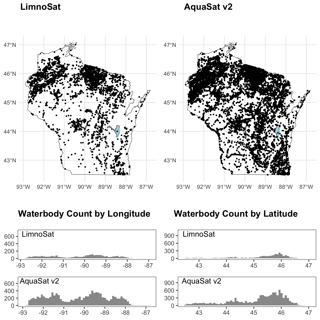
Figure 3.2: Deepest point of Wisconsin lakes included in LimnoSat-US defined by the Hydrolakes data product (left) and those included in AquaMatch via lakeSR defined by the NHDPlusV2 data product (right). Deepest point for each lake is indicated with a black dot, spatial histogram of density by longitude and latitude presented below the maps.
3.2 siteSR Acquisition Locations
Technical Note
This process is orchestrated in the targets group a_compile_sites in the
siteSR workflow. The primary output file of this process is the siteSR site file
(siteSR_collated_WQP_NWIS_sites_with_NHD_info_2025-06-04.csv).
Background
The acquisition locations within siteSR are defined using the {dataRetrieval}
package (DeCicco et al. 2025) functions whatWQPsites() and whatNWISsites() which
are stored in the siteSR site file. All sites were filtered for those that
represent surface water according to the populated MonitoringLocationTypeName
for WQP sites and site_tp_cd (“site type code”) for NWIS sites. These sites
were supplemented by those for which we have harmonized parameter data from the
AquaMatch parameter harmonization pipeline but that did not appear in the
whatWQPsites() query. Absence of a limited number of sites in the
whatWQPsites() query is expected and is due to the dynamic nature of the WQP,
since some of the AquaMatch parameter harmonization was queried at a different
time than the query for siteSR. The siteSR pipeline collates these sites, then
reduces that collation to only distinct sites defined by organization
identifier, monitoring location identifier, WGS84 latitude and WGS84 longitude.
Across the WQP, NWIS, and the harmonization pipeline, there are currently
1,207,214 sites in the United
States and territories for which we attempt to create “stacks” of remote sensing
data. A “stack” refers to all the remote sensing data available during a time
period of interest at a single site.
Every site in the WQP has a MonitoringLocationTypeName associated with it.
Within siteSR there are
1,015,748
sites from the WQP.
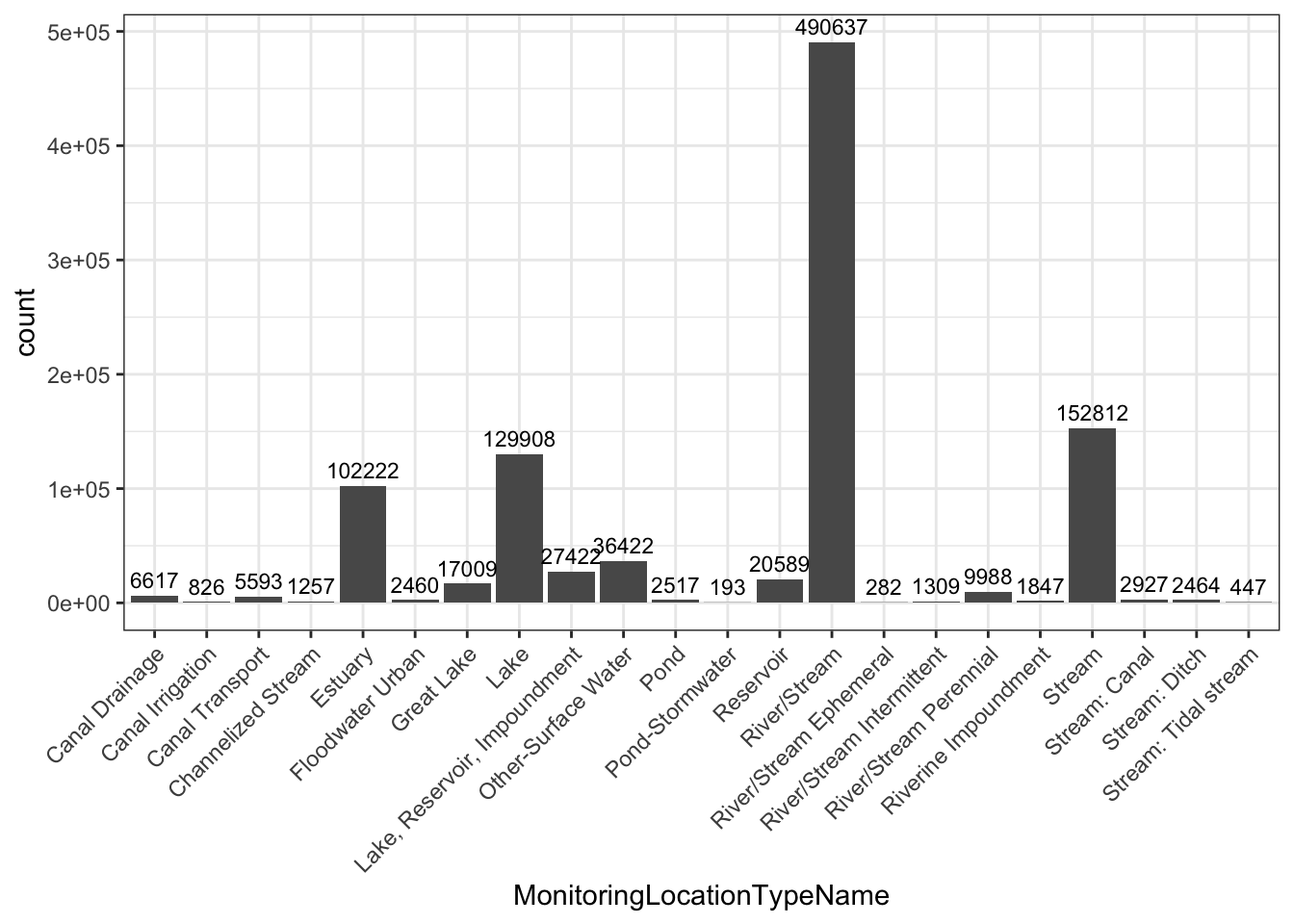
Figure 3.3: Water Quality Portal data location types present in siteSR. Unique WQP monitoring location count above bar, divided by MonitoringLocationTypeName.
Similarly, every site in the NWIS database has a site type code (site_tp_cd)
associated with it. Within siteSR there are
191,466
sites from NWIS.
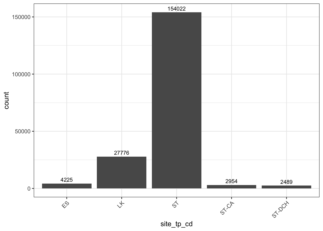
Figure 3.4: National Water Information System data location types present in siteSR. Unique NWIS monitoring location count above bar, divided by site type. ST = Stream, ST-CA = Canal, ST-DCH = Ditch, LK = Lake/Reservoir, ES = Estuary.
3.2.1 Harmonizing siteSR site types
In order to harmonize the site types across WQP and NWIS data providers, we
attempt to generalize site types into five groups: Lake/Reservoir/Pond, Stream,
Canal/Ditch, Estuary, Other. These designations are stored in the column
harmonized_site_type in the siteSR site file.
| AquaMatch harmonized_site_type | NWIS site_tp_cd | WQP MonitoringLocationTypeName |
|---|---|---|
| Lake/Reservoir | LK | contains “lake”, “reservoir”, or “impoundment” |
| Pond | no associated code | contains “pond” |
| Stream | ST | contains “stream” |
| Canal/Ditch | ST-CA, ST-DCH | contains “canal” or “ditch” |
| Estuary | ES | Estuary |
| Other | all remaining codes | all remaining codes |
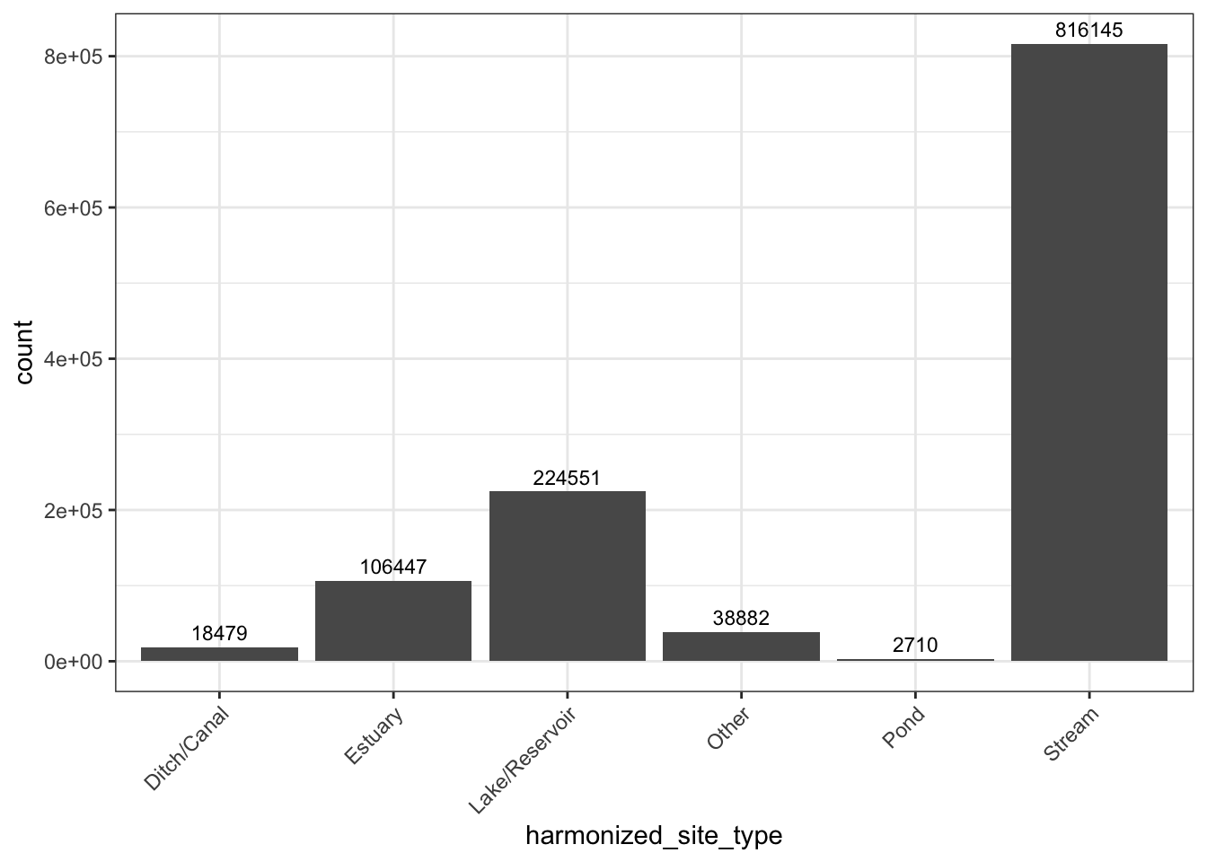
Figure 3.5: AquaMatch harmonized_site_type categories provided in siteSR. Unique AquaMatch site count above bar, divided by harmonized_site_type.
3.2.2 Assignment of NHD flowline and waterbodies
HUC8 assignment
For each siteSR location, we attempt to assign HUC8’s using the get_huc()
function in the {nhdplusTools} (Blodgett and Johnson 2023) package in R. While there is a
column (HUCEightDigitCode) provided with WQP sites query that attributes a
HUC8 to sites, some of them are missing data (n =
10577)
and some of them differ from those obtained using the reported location latitude
and longitude and the get_huc() function (n =
25628).
Additionally, NWIS sites are not associated with HUC8’s when queried and this
process assigns a HUC8 as a value add to downstream users. These HUC assignments
are stored in the assigned_HUC column in the siteSR site file. After this
process, only 1641
sites remained without a HUC8 assignment using the nhdplusTools method. Most of
these sites were coastal sites outside of the extent of NHD boundaries (n =
1357) or were
assigned a HUC8 in the WQP data and were estuaries, but were unable to be
assigned in this process (n =
284). All sites
remain in siteSR, but those without an assigned HUC8 using this process
(flag_HUC of 3 or 4) will have no NHD feature attribution information.
In siteSR, we provide a flag_HUC8 column in the siteSR site file with the
following code definitions:
0: HUC8 reported in WQP site information, matches nhdplusTools assignment
1: HUC8 successfully assigned using nhdplusTools, no HUC8 reported in HUCEightDigitCode
2: HUC8 mismatch between Water Quality Portal HUCEightDigitCode assignment and nhdplusTools assignment
3: HUCEightDigitCode was assigned to a site type of estuary, but not able to be assigned using the nhdplusTools method
4: HUC8 unable to be assigned for site location using the nhdplusTools method and was not provided by WQP/NWIS site information
NHD Waterbody Feature Assignment
Using the assigned HUC8 information to iterate, we then can use {nhdplusTools}
to assign waterbodies and flowlines to sites within the CONUS and data from The
National Map best resolution files (e.g. US Geological Survey 2023b) for sites outside
of CONUS by HUC4. For all sites with a harmonized_site_type of Lake/Reservoir,
Pond, Estuary or Other, we assign NHD ids to each point for the NHD waterbody
feature it is contained by or the NHD feature it is closest to. The NHD
waterbody layer has been filtered to only contain Lake, Ponds, Reservoirs, and
Estuaries (NHD feature types 390, 436, 493) when performing this task. We flag
(flag_wb “waterbody flag” in the siteSR site file) the results of this
assignment as follows:
0: point inside NHD waterbody feature polygon
1: point within GEE buffer distance (default 200 meters for siteSR) of the NHD waterbody feature
2: point between GEE buffer distance and 500 meters of the NHD waterbody feature polygon
3: point unable to be assigned to waterbody feature (it is > 500 meters away from the closest NHD waterbody feature polygon)
4: point does not have HUC8 assignment or harmonized_site_type is not Lake/Reservoir, Pond, Estuary, or Other. No NHD waterbody feature is assigned.
For all points with a flag value of 0, 1, and 2, we provide the NHD identifier
(wb_nhd_id in the siteSR site file) for the polygon the monitoring location is
associated with (comid for NHDPlusV2 and permanent identifier for NHD Best
Resolution), for all points with a flag value of 1, 2, and 3, we provide the
distance (in meters) to the nearest NHD waterbody (dist_to_wb in siteSR site
file) of feature type 390, 436, or 493. For waterbodies with a flag of 0, we
provide distance to shore (dist_to_shore in siteSR site file).
We follow lakeSR’s implementation of flags for shoreline proximity for these
sites. For sites with a distance to shore value, we also provide a diagnostic
column that indicates likelihood of shoreline contamination within the scope of
Landsat extraction. To determine the possibility of shoreline contamination, we
add the site buffer used for GEE extraction (200 m for siteSR) to the pixel size
of the sensor used for reflectance detection. For optical sensor bands (Red,
Green, Blue, NIR, SWIR) we use the site buffer plus 30 meters
(flag_optical_shoreline). For thermal sensor bands, we create 3 flag columns
for each sensor’s native thermal resolution (Landsat 4/5: TM 120m
flag_thermal_TM_shoreline, Landsat 7: ETM+ 60 m flag_thermal_ETM_shoreline,
Landsat 8/9: TIRS 100m flag_thermal_TIRS_shoreline). These flags are binary
values in the siteSR site file for sites with a flag_wb value of 0 (indicating
that the site is inside of the NHD waterbody feature):
0: unlikely shoreline contamination (distance to shore is greater than the sum of the site buffer and pixel size)
1: possible shoreline contamination (distance to shore is less than or equal to sum of the site buffer and pixel size)
NHD Flowline Feature Assignment
Flowlines are assigned to all siteSR sites. NHD flowlines are filtered to
contain streams/rivers, canals, and artificial paths (that is flowlines within
NHD waterbody features) (NHD feature types 460, 336, and 558). We flag
(flag_fl in the siteSR site file) the results of this assignment as follows:
0: point <= 100 meters from nearest NHD flowline feature
1: point between 100 meters and GEE buffer distance (default 200 meters for siteSR) to nearest NHD flowline feature
2: point between GEE buffer distance and 500 meters from nearest NHD flowline feature
3: point unable to be assigned to a NHD flowline for a stream/canal site because distance to nearest NHD flowline feature > 500 meters
4: point is a lake/reservoir/pond/other/estuary (defined by harmonized_site_type) and is > 500 meters away from nearest NHD flowline feature
5: point does not have HUC8 assignment. No flowline assigned.
For all points with a flag 0-3 we provide the NHD identifier (fl_nhd_id in the
siteSR site file) for the flowline the monitoring location is associated with
(comid for NHDPlusV2 and permanent identifier for NHD Best Resolution), for all
points with a flag value of 0-4, we provide the distance (in meters) to the
nearest NHD flowline (dist_to_fl in siteSR site file) of feature type 460,
558, 336.
Multiple Intersecting NHD Features
For all sites with an assigned_HUC8, we calculate how many waterbodies or
flowlines are within the buffer distance set in the siteSR GEE configuration
file (stored in number_int_wb for number of waterbodies and number_int_fl
for flowlines in the siteSR site file). Any site that has more than one
waterbody and/or flow line within the buffer distance may be including
reflectance data from another surface water source. Within the context of
siteSR, we do not investigate what, if any, impacts multiple waterbodies,
flowlines, or combinations thereof have on the validity of the reflectance data
or thermal data summary.
We provide these identifiers and additional metadata about the sites to help users make informed decisions about remote sensing data quality (specifically, related to edge/shoreline contamination) and NHD common unique identifier (COMID) or permanent identifier attribution to individual sites and any available flags to assess uncertainty to those assignments or the buffered area relative to the site.
Note that the siteSR site file noted above collates NHD Best Resolution
permanent identifiers and NHDPlusV2 comid values into a column for waterbody
features wb_nhd_id and one for flowline features fl_nhd_id. The upstream
source of the NHD data is noted in wb_nhd_source and fl_nhd_source columns
to allow users to know whether the value in the wb_nhd_id or fl_nhd_id
columns is a NHD Best Resolution permanent identifier (NHDBestRes) or a
NHDPlusV2 COMID (NHDPlusV2).
3.2.3 Assessing for remote sensing visibility
For siteSR, we will acquire Landsat stacks for all sites deemed “visible” by remote sensing irrelevant of site type. Note that this is different from lakeSR, where we only acquire data for lakes, reservoirs and ponds according to the NHD. This was a functional choice, as estuary extents are limited in the NHD (and when present the technique to determine the POI may not be appropriate).
We use the European Commission’s JRC Global Surface Water Mapping Layers v1.4 (Pekel et al. 2016) to determine whether or not sites are visible by remote sensing (RS visible) and should therefore be sent through the GEE data acquisition process detailed in Section 6. The JRC surface water dataset is a compilation of 38 years of the Landsat record and enumerates the proportion of time a single 30x30 meter pixel has the presence of water. As long as a siteSR site location has at least one pixel designated as being occupied by water at least 80% of the time during that 38 year period within a 200 meter radius, we include the site in the list for which we acquire Landsat stacks.
After assessing for remote sensing visibility, 395,307 sites were deemed to be visible by remote sensing (67.3% loss of sites).
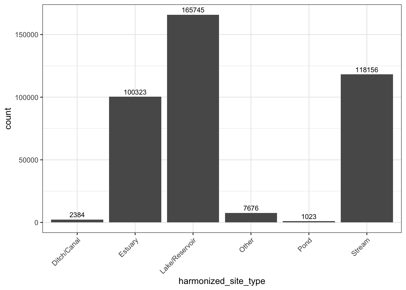
Figure 3.6: siteSR data location types present in the dataset after filtering for those that are deemed visible by remote sensing. Count of sites provided above bar, arranged by harmonized_site_type.
3.2.4 siteSR updates in AquaMatch
In our updated workflow, we acquire and provide the historical Landsat stacks for all sites available from the WQP and NWIS, regardless of whether they are associated with a specific in situ observation present in our harmonization pipeline. In the previous iteration, we only provided a matchup dataset for in situ data. Assigning NHD flowlines and waterbodies to all siteSR sites is also a feature introduced in AquaMatch.